Media
Information

2025 / 10 / 28
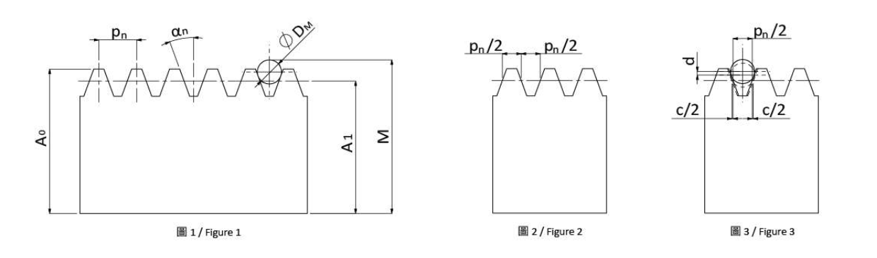
To measure the tooth thickness tolerance of a rack, an over-pin measurement method is used. Two pins are inserted between the rack teeth, and the distance between the top of the pins to the bottom of the rack is measured, as illustrated in Figure 1. This distance is defined as the over-pin dimension (M).
The over-pin dimension can be calculated by the following formula:
M = A1 + (DM / 2) × (1 / sin αn + 1) - (mn / 4tan αn)
Normal pitch: Pn = mn × π
When the rack and pinion mesh, the theoretical line of contact is called the pitch line. When the pitch line is at its ideal position, the tooth thickness equals Pn / 2. To ensure smooth meshing between the rack and pinion, the tooth thickness must be maintained within a specific range, defined as the tooth thickness tolerance.
According to theoretical calculations, for each reduction in tooth thickness by c / 2, the corresponding decrease in tooth height (d) can be calculated using the following formula:
d = (c / 2) × tan αn
| c | d | Unit |
|---|---|---|
| 0.01 | 0.0137 | mm |
| 0.02 | 0.0275 | mm |
This relationship also allows engineers to estimate the variation in gear backlash when tooth thickness changes.
The table below lists the standard pin diameters and corresponding over-pin dimensions for different module sizes in YYC racks.
| Module (M) | Pin Diameter ØDM | Over-Pin Dimension A0 | Pin No. |
|---|---|---|---|
| 1.5 | ø3 | 18.149 | 17 |
| 2 | ø4 | 25.532 | 24 |
| 2.5 | ø5 | 25.915 | 29 |
| 3 | ø6 | 31.298 | 29 |
| 4 | ø8 | 42.064 | 39 |
| 5 | ø10 | 42.830 | 39 |
| 6 | ø12 | 52.396 | 49 |
| 8 | ø16 | 85.128 | 79 |
| 10 | ø20 | 106.659 | 99 |
Figure 1 illustrates the over-pin measurement principle, while Figures 2 and 3 demonstrate the variation in tooth thickness and backlash. This measurement method provides a practical way to assess rack manufacturing precision and serves as an important reference for adjusting backlash during rack-pinion assembly.