Media
Information

2025 / 10 / 29
To ensure stable, safe, and efficient rack and pinion operation, proper selection and precise calculation are essential. The following 5-step process outlines how YYC engineers perform rack and pinion drive system selection and evaluation.
Before choosing the rack and pinion pair, identify the application type, motion direction, and main load parameters. These initial values form the basis for further calculation.
| Symbol | Description | Unit / Remark | Example |
|---|---|---|---|
| Application | Type | — | Machine Tool Movement |
| Movement | Horizontal / Vertical | — | Horizontal |
| m | Maximum Load Weight | kg | 2500 |
| μ | Coefficient of Friction | — | 0.01 |
| v | Maximum Linear Speed | m/min | 60 |
Enter rated specifications for the gearbox and motor to define the torque and speed foundation for the system design.
| Symbol | Description | Unit | Example |
|---|---|---|---|
| NG | Gearbox Rated Speed | rpm | 3000 |
| TG | Gearbox Rated Torque | Nm | 180 |
| i | Gear Ratio | — | 10 |
| NM | Motor Rated Speed | rpm | 3000 |
| TM | Motor Rated Torque | Nm | 20 |
Define operational load factor KA and safety factor SB based on operating conditions. Input acceleration and deceleration parameters as follows.
| Symbol | Description | Unit | Example |
|---|---|---|---|
| KA | Operating Load Factor | — | 1 |
| SB | Safety Coefficient | — | 1 |
| α₁ | Acceleration | m/s² | 2 |
| t₁ | Acceleration Time | s | 0.5 |
| α₂ | Deceleration | m/s² | 2 |
| t₂ | Deceleration Time | s | 0.5 |
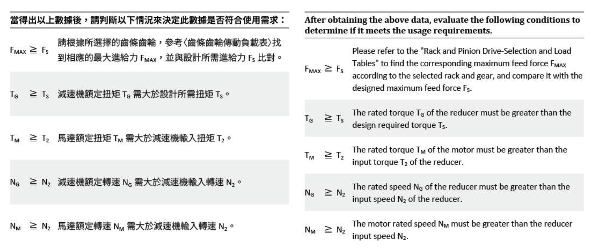
After computation, verify that all parameters meet the following conditions to ensure proper and safe operation:
This application meets the requirements.
| Condition | KA |
|---|---|
| Uniform | 1.0 |
| Medium | 1.25 |
| Heavy | 1.75 |