Media
Information

2026 / 08 / 26
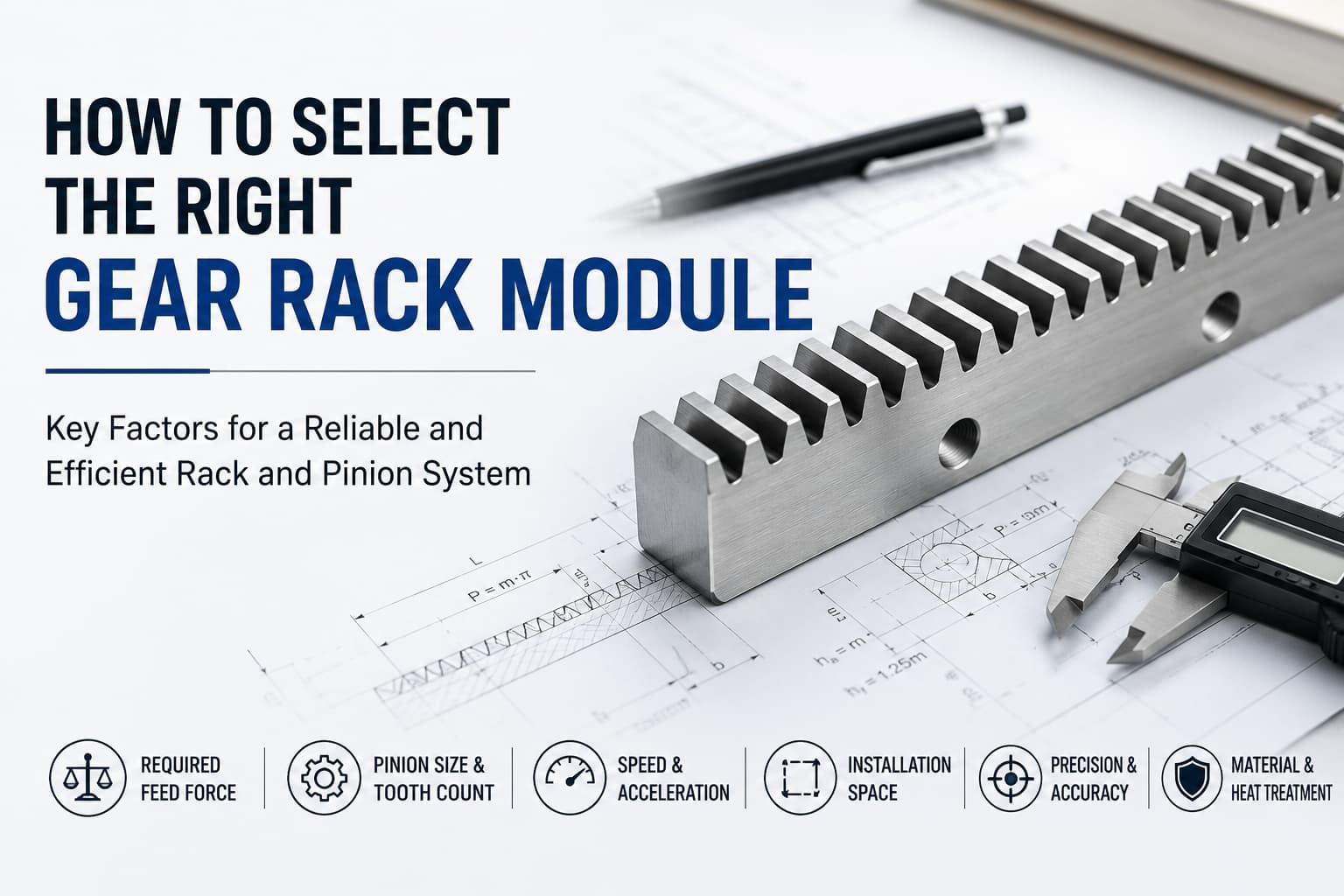
Selecting a gear rack involves more than choosing between a straight or helical tooth profile. One of the most important specifications is the gear rack module, which determines the size of the teeth and has a direct relationship with the dimensions and load capability of the rack-and-pinion drive.
A module that is too small may not provide sufficient capacity for the required feed force. Choosing a larger module than necessary, however, can increase the size of the pinion and transmission components without providing a meaningful advantage for the application.
So, how do you determine the right gear rack module? This guide explains what module means, the factors engineers should evaluate, and why module selection should be considered as part of the complete rack-and-pinion system.
The module (M) is a fundamental parameter used to define metric gear tooth size. In simple terms, a larger module means larger teeth, while a smaller module means smaller teeth.
For a mating rack and pinion to engage correctly, they must share compatible tooth geometry — this means not only the same module but also the same pressure angle. The basic rack tooth profile is defined by DIN 867, and a 20° pressure angle is the most common standard. A rack and pinion with different modules, or with different pressure angles, will not mesh correctly even if every other specification matches.
The module therefore affects not only the rack itself but also the dimensions of the mating pinion and the overall transmission design.
For engineers, module is an important starting point because it influences:
However, module alone does not determine whether a rack is suitable for an application. Material, heat treatment, tooth finishing, precision grade, pinion specifications, lubrication, and actual operating conditions must also be considered.
For available product configurations, see YYC's precision gear racks.
When a pinion drives a rack, force is transmitted through the meshing teeth. The selected tooth geometry must therefore be capable of supporting the required operating conditions.
In general, increasing the module increases tooth size and can support applications requiring greater transmission capacity. But simply choosing the largest available module is not necessarily the best approach.
A larger module can also mean a larger mating pinion and more space required for the transmission assembly. This may be unnecessary in applications where compact dimensions or finer mechanical design are priorities.
Key Point: The objective is not to select the largest module, but to select an appropriate module for the required feed force and complete drive configuration.
The following comparison provides a useful starting point:
| Selection Factor | Smaller Module | Larger Module |
|---|---|---|
| Tooth size | Smaller | Larger |
| Transmission capacity | Generally lower | Generally higher |
| Pinion dimensions | Can be more compact | Generally larger |
| Installation space | Easier to accommodate in compact designs | Requires more space |
| Typical design priority | Compact and lighter-duty transmission | Higher-force and heavy-duty transmission |
| System selection | Must be verified against actual load and drive conditions | Must still be checked against speed, torque, and system requirements |
This comparison should be treated as a general design guideline rather than a module selection chart.
Two racks with the same module can have different allowable feed forces depending on their material, heat treatment, tooth processing, and other design specifications.
One of the first parameters to determine is how much force the rack must transmit.
The required feed force is influenced by factors such as:
Applications involving heavier moving structures or higher process forces generally require greater transmission capacity.
This is why module selection should begin with the actual force requirements of the machine, rather than simply copying the module used in another application.
The rack does not operate independently. It must mesh with a compatible pinion.
The module and number of pinion teeth influence the pinion pitch diameter. As the module increases, a pinion with the same number of teeth will also become larger.
This affects:
For this reason, engineers should evaluate the rack and pinion together rather than selecting the rack first and considering the pinion afterward.
YYC provides a range of cylindrical pinions that can be evaluated together with the selected rack according to application requirements.
Motion requirements are another important consideration.
Industrial systems may require very different combinations of:
A system designed for slow, heavy-duty movement has different transmission requirements from one designed for frequent high-speed positioning.
Module selection should therefore be checked together with the drive ratio, pinion dimensions, motor speed, gearbox output, and required linear velocity.
A larger module does not only mean larger rack teeth. It can also affect the size of the mating pinion and surrounding drive components.
In compact machinery, this can become an important design constraint.
Before increasing module size, engineers should check whether sufficient space is available for:
The goal is to achieve the required transmission capacity without unnecessarily increasing the mechanical envelope.
Module is only one factor affecting rack performance.
Two products with the same module may offer different capabilities because of differences in:
For example, a hardened and ground rack is designed for different performance requirements than a milled rack of the same module.
This is why selecting a module without checking the actual rack series and specifications can lead to an incorrect conclusion.
Module should also be evaluated alongside the required positioning and transmission performance.
Applications such as machine tools and precision automation may place greater emphasis on:
In these situations, simply increasing the module does not automatically improve positioning accuracy.
Where minimal backlash is critical, the drive layout matters as much as the module. High-precision systems often use a preloaded or twin-pinion arrangement to reduce backlash, which places additional emphasis on consistent tooth and pitch accuracy across the rack.
The appropriate accuracy grade, tooth treatment, rack-and-pinion matching, mounting accuracy, and system rigidity are equally important.
A common oversimplification is:
“Higher load = choose a larger module.”
While load is certainly an important factor, this rule alone is insufficient for engineering selection.
Consider two systems with similar loads:
System A operates slowly with moderate acceleration and ample installation space.
System B operates at higher speed, accelerates frequently, and has limited installation space.
Even if their nominal loads are similar, their optimal rack-and-pinion configurations may be different.
A proper selection should therefore evaluate the combination of:
Load + Feed Force + Speed + Acceleration + Pinion + Reducer + Motor + Accuracy + Duty Cycle + Installation Conditions
rather than relying on module alone.
Many linear applications require travel lengths longer than a single rack. In these cases, multiple racks are installed end-to-end, and the accuracy of the joint between racks becomes a critical selection factor that does not apply to a single gear or a short rack.
At each joint, the tooth pitch must remain continuous across the transition so the pinion runs smoothly from one rack into the next without a bump, pitch error, or noise. Achieving this depends on the manufacturing accuracy of the rack ends, correct installation, and, for higher-precision applications, matched or mounting-referenced racks.
When planning a long-travel axis, engineers should consider the required accuracy grade, the jointing method, and the mounting reference alongside the module, rather than treating the racks as independent segments.
After identifying a suitable module range, the next step is to verify the complete rack-and-pinion drive.
This involves evaluating parameters such as:
The rack and pinion must be considered together. The selected module determines compatible tooth geometry, while the pinion size and number of teeth also influence pitch diameter, travel per revolution, and overall drive configuration.
This is where module selection and rack-and-pinion system calculation become two related but different engineering tasks.
Module selection helps determine an appropriate tooth size and rack family. System calculation then verifies whether the selected rack, pinion, gearbox, and motor can meet the actual operating requirements.
Related Reading: For a step-by-step explanation covering feed force, torque, speed, gearbox, and motor considerations, read YYC's Rack and Pinion Selection and Calculation.
YYC Machinery provides a broad selection of precision gear racks for different motion requirements.
The YYC Standard Rack Series covers modules from M1 to M10, with options including:
This range allows designers to evaluate more than module alone and select a rack according to the required combination of tooth profile, material, precision, heat treatment, length, and transmission capacity.
For applications requiring a complete rack-and-pinion drive, designers can also evaluate YYC's Cylindrical Pinion Series together with the selected rack.
YYC also provides selection tools that help narrow down rack and pinion options according to parameters such as module, tooth profile, material, precision grade, heat treatment, and length.
With more than 45 years of precision gear manufacturing experience, YYC Machinery supports customers in evaluating rack and pinion solutions for different industrial motion requirements.
Choosing the right gear rack module starts with understanding the required feed force, but it should never end there.
The appropriate module depends on the interaction between load, pinion dimensions, speed, acceleration, installation space, rack construction, accuracy requirements, and the complete drive system.
Instead of asking only “Which module can carry this load?”, a better engineering question is:
“Which rack and pinion configuration provides the required force, speed, accuracy, and service life within the available machine design?”
With more than 45 years of precision gear manufacturing experience, YYC Machinery offers rack and pinion products across a wide range of modules, tooth profiles, materials, precision grades, and heat-treatment options.
If you are evaluating a gear rack for a new machine or automation project, contact YYC Machinery to discuss your operating conditions and determine a suitable rack and pinion configuration for your application.

