
When selecting a gear rack, it is common practice to simply specify DIN 5, DIN 6 or DIN 8. For a linear axis, however, a more sound approach is to first deduct the errors from gearbox backlash, pinion runout, rack mounting, structural deflection, feedback resolution and thermal expansion, and then determine what share of the axis's allowable positioning error can be allocated to the rack.
Based on the total pitch deviation values published on the YYC website, this article shows how to specify rack accuracy by numerical values rather than by grade, so as to avoid over-specification and to avoid expecting the rack to compensate for shortcomings elsewhere in the drive train.
1. Specify Tolerance Values Instead of Grades
An accuracy grade is a shorthand for communication and should not be the sole acceptance criterion. Two racks both labeled “DIN 6” may mean different things if the referenced standard and edition, the measured characteristics, the evaluation length or the reference temperature differ.
YYC racks are manufactured to the DIN 867 basic rack tooth profile, with tolerances and accuracy grades in accordance with DIN 3962, DIN 3963 and DIN 3967.
ISO 1328-1:2013 defines the flank tolerance classification for individual cylindrical involute gears. Even when the numbers match, DIN and ISO grades must not be treated as equivalent, and “DIN 6” as labeled by different suppliers does not necessarily guarantee the same values. Before comparing products, confirm the following:
- The referenced standard and edition
- Whether the value refers to a single pitch, a specific measuring length, or the full rack length
- The value and evaluation length of the total pitch deviation Fp
- Inspection method, inspection conditions and reference temperature
- Whether the specification applies before or after heat treatment and final machining
- Whether pitch control at rack joints is included
Within the same grading system, a lower grade number means tighter tolerances; however, this does not mean the assembled axis will achieve the same accuracy.
2. Total Pitch Deviation of YYC Racks by Accuracy Grade
Figure 1 and Table 1 show the total pitch deviation Fp published on the YYC website for standard racks (module 2, helical teeth), allowing comparison across accuracy grades and lengths.
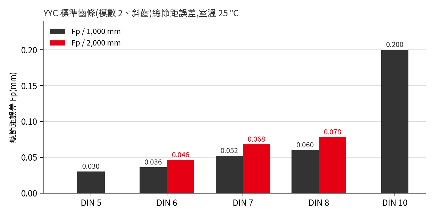
Table 1 Specifications and Fp / 1,000 mm by accuracy grade
| Accuracy Grade | Tooth Finish | Heat Treatment / Hardness | Material | Fp / 1,000 mm |
|---|---|---|---|---|
| DIN 5 | Ground | Induction hardened, HRC 50–55 | S50C | 0.030 mm |
| DIN 6 | Ground | Induction hardened, HRC 50–55 | S50C | 0.036 mm |
| DIN 7 | Ground | Induction hardened, HRC 50–55 | S50C | 0.052 mm |
| DIN 8 | Precision milled | None | S50C | 0.060 mm |
| DIN 10 | Precision milled | Induction hardened, HRC 50–55 | S50C | 0.200 mm |
Note: Values are taken from the YYC website product pages for module 2 helical racks, referenced to a room temperature of 25 °C. Fp for 2,000 mm racks: DIN 6 is 0.046 mm, DIN 7 is 0.068 mm, DIN 8 is 0.078 mm. Fp increases with module; for example, DIN 6, module 5, 1,000 mm is 0.040 mm. If your acceptance test is referenced to 20 °C, please agree on this in advance. Actual specifications are subject to the product page, drawing, or specifications confirmed by both parties.
DIN 5 is available only in 1,000 mm lengths (modules 2 and 3); some modules in DIN 6 to DIN 10 are also available in 2,000 mm. Available lengths for each module are subject to the product page.
The data show that doubling the rack length does not double Fp. For DIN 6, the Fp of a 2,000 mm rack is 0.046 mm, less than twice the 1,000 mm value (0.072 mm). In long-stroke applications, rack length is therefore as important a parameter as accuracy grade; see Section 4.
3. Building an Axis Error Budget
Selection should start from the requirement at the tool center point, carriage or working position, not from the rack catalog. First define the positioning error allowed for the whole axis over the specified stroke and operating conditions.
The positioning error of a rack-driven axis does not come from the rack alone; it also includes rack joints, pinion runout, gearbox lost motion, mounting accuracy, structural deflection, thermal expansion and the control system (Figure 2). An allowance should be assigned to each error source. How the errors are combined (simple summation or statistical methods) is decided by the machine builder, based on measured data or a validated engineering model.
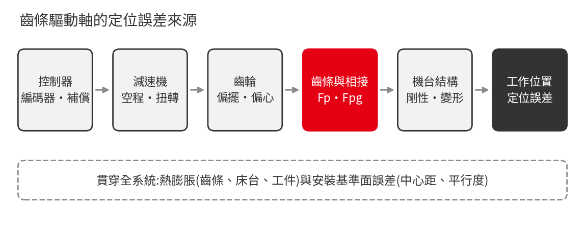
Table 2 Error sources and control methods
| Error Source | Main Causes | Control Method |
|---|---|---|
| Rack | Total pitch deviation and local pitch variation | Set tolerances by evaluation length and verify inspection data |
| Rack joints | Pitch discontinuity, height offset or angular deviation at joints | Position with a mounting gauge and check every joint |
| Pinion | Runout, tooth profile accuracy, mounting eccentricity | Control bore or spline fit, runout and shoulder accuracy |
| Gearbox | Lost motion, torsional deflection, ratio error | Use backlash or lost-motion data measured under actual load torque |
| Mounting surface | Center distance, parallelism, mounting reference surface error | Machine the mounting reference surface and check rack alignment after fastening |
| Structure | Deflection of gantry, bearings, brackets or base | Calculate stiffness and verify under bidirectional loads |
| Thermal effects | Thermal expansion of rack, machine bed and workpiece | Define the temperature range and apply compensation where necessary |
| Controller | Encoder resolution, following error, compensation table | Plan the feedback architecture and calibration method |
Once the rack's allocation has been determined, selection requires a clear numerical limit rather than a qualitative description such as “high precision”.
4. Long Strokes and Joining Multiple Racks
When the stroke exceeds the length of a single rack, joint errors must be included in the evaluation. Even if each rack has good tooth quality, the axis may still accumulate excessive error or exhibit periodic vibration at each joint.
4.1 Estimating Joined-Rack Error
According to the YYC catalog, the error of multiple joined racks can be estimated as follows:
When two rack lengths are combined, use the Fp corresponding to each rack's length.
4.2 Calculation Example: 3,000 mm Stroke
Calculation conditions:
- Axis stroke: 3,000 mm, without pitch error compensation
- Maximum allowable positioning deviation of the axis: 0.20 mm, of which 0.12 mm is allocated to joined-rack error and the remaining 0.08 mm to other error sources
- Rack: module 2, helical teeth; gauge: DIN 6 mounting gauge, Fpg = 0.025 mm (DIN 5 joints also use the DIN 6 gauge)
Figure 3 compares the accumulated joined-rack error of three rack configurations; the calculations are listed in Table 3.
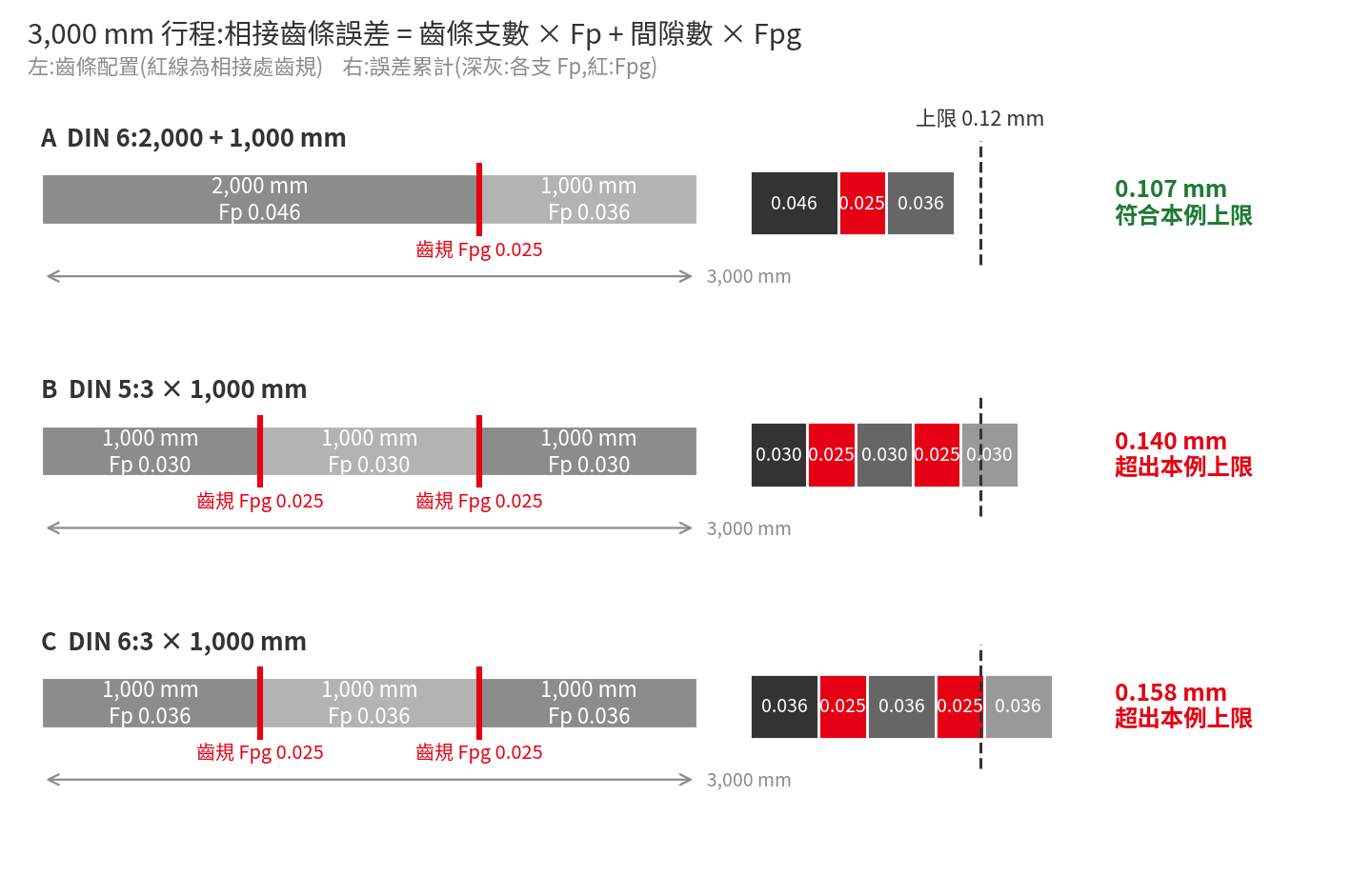
Note: Fp and Fpg in the figure are upper tolerance limits, and the joined-rack error is the worst case obtained by simply adding these limits; it is not measured accuracy. The 0.12 mm allocation is an assumption for this example, which is intended to illustrate the selection method.
Table 3 Joined-rack error calculation results
| Configuration | Rack Combination | Calculation | Result | Judgment |
|---|---|---|---|---|
| A | DIN 6: 2,000 mm + 1,000 mm | 0.046 + 0.036 + 1 × 0.025 | 0.107 mm | Pass |
| B | DIN 5: 3 × 1,000 mm | 3 × 0.030 + 2 × 0.025 | 0.140 mm | Exceeds |
| C | DIN 6: 3 × 1,000 mm | 3 × 0.036 + 2 × 0.025 | 0.158 mm | Exceeds |
Configuration A has the fewest joints, with an accumulated error of 0.107 mm, within the allocated limit. Configuration B uses DIN 5, which has higher single-rack accuracy, but requires 3 racks and 2 joints, giving 0.140 mm; Configuration C gives 0.158 mm. The gauge error added at each joint can offset the advantage of higher single-rack accuracy, which cannot be judged from the grade number alone.
Note that this example is intended to demonstrate the selection method and does not imply that the racks in Configurations B and C lack accuracy. Table 3 uses upper tolerance limits throughout; the joined-rack error is the worst case obtained by simply adding these limits, and the 0.12 mm allocation is also an assumption. If the axis requirement is less strict, or if pitch error compensation is used, the same configurations may still meet the requirement.
The formula above adds the errors directly and is therefore a conservative estimate; the actual joint error depends on the error distribution of each rack and the quality of the joint installation. The remaining 0.08 mm must cover pinion mounting, gearbox lost motion, linear guide alignment, structural deflection, thermal expansion and control error. If these items together already exceed 0.08 mm, upgrading the rack grade alone will not achieve the target.
4.3 Key Points for Joining Racks
When joining multiple racks, check the following three items separately:
- Single-rack pitch performance: total pitch deviation and local pitch variation of each rack
- Joint continuity: the actual pitch from the last tooth of one rack to the first tooth of the next
- Mounting reference continuity: rack mounting reference surface, tooth height position, parallelism and straightness along the machine
The fewer the joints, the lower the chance of pitch discontinuity, which is also a design recommendation in the YYC catalog. During installation, position each joint with a YYC mounting gauge, tighten the bolts in sequence, and recheck each joint after final torque tightening. Measuring the mounting reference surface alone is not sufficient, as the meshing condition at the joints is what matters most in operation.
When absolute positioning is used over the full stroke, accumulated error is most critical. If the process consists mainly of short incremental moves, local pitch variation, reversal behavior and repeatability may have a greater impact.
4.4 Defining Acceptance Criteria
Acceptance criteria should clearly define the following:
- Accuracy or deviation limits
- Evaluation length and measurement reference
- Measurement direction and load conditions
- Reference temperature (YYC published values are referenced to 25 °C)
- Whether the requirement applies to the rack itself, the installed rack, or the whole axis
- Whether compensation is permitted in the final accuracy report
5. Positioning Accuracy, Repeatability and Backlash
The following performance items have different definitions and should not be used interchangeably:
Table 4 Performance items and their relationship to rack accuracy grade
| Performance Item | Definition | Effect of a Higher Rack Accuracy Grade |
|---|---|---|
| Positioning accuracy | Difference between commanded and actual position over the full stroke | A smaller total pitch deviation helps, but the final result still depends on the whole axis and compensation |
| Repeatability | Ability to return to the same position under the same conditions | Better meshing consistency may help, but servo tuning, friction, temperature and structure are equally important |
| Reversal error | Difference when approaching the same position from opposite directions | A higher rack accuracy grade alone cannot eliminate gearbox or meshing backlash |
| Smoothness | Speed fluctuation, vibration and transmission uniformity | Tooth profile quality helps, but pinion quality, alignment, lubrication and stiffness are equally critical |
A high-precision rack is not the same as zero backlash. To reduce reversal error, the center distance must be controlled and, as required, combined with preloaded dual pinions, a low-backlash gearbox, sufficient structural stiffness and appropriate servo control. The rack should also be paired with a YYC pinion of comparable accuracy.
6. When a Higher Rack Accuracy Grade Is Worthwhile
Upgrading the rack accuracy grade is meaningful only when rack error accounts for a significant share of the axis error and other elements will not offset the improvement.
Table 5 Application conditions and recommended approach
| Application Condition | Recommended Approach |
|---|---|
| Long-distance absolute positioning with tight positioning tolerance | First review the joined-rack error over the full stroke, including rack length and number of joints |
| High-speed contouring or synchronized axes | Also evaluate local pitch consistency, pinion accuracy, dynamic stiffness, lubrication and servo response |
| Frequent reversals under load | Treat backlash, gearbox lost motion, mesh preload and torsional stiffness as primary design conditions |
| Large temperature variation or process heat | Calculate thermal expansion first, then decide whether to upgrade the rack grade, and define the compensation method and reference conditions |
| General handling with moderate positioning tolerance | If maximum feed force, mounting and service life meet requirements, a precision-milled rack may be sufficient |
| Poor mounting reference or insufficient frame stiffness | Improve the machine structure and mounting first, then consider upgrading the rack grade |
Order-of-Magnitude Estimate of Thermal Expansion
The coefficient of linear expansion of ordinary carbon steel or low-alloy steel is approximately 11–12 µm per meter per °C. For a 3 m length with a uniform temperature rise of 10 °C:
This free thermal expansion already exceeds the 0.20 mm allowed for the whole axis in the Section 4 example. Actual deformation depends on the rack material, temperature distribution, mounting constraints, reference structure and feedback configuration, and should be calculated for the actual machine.
7. Information Required for Quotation
To provide an appropriate selection recommendation, please include the following information in your inquiry:
- Total stroke and effective positioning length
- Required positioning accuracy, repeatability and reversal error
- Maximum speed, acceleration, duty cycle and reversal frequency
- Moving mass, external process forces and required feed force
- Rack mounting orientation, module, tooth type and available mounting space
- Pinion size, reduction ratio, gearbox lost motion and motor data
- Number of racks and length of each
- Mounting reference surface tolerance and planned joining method
- Operating temperature range, dust environment, lubrication method and expected service life
- Feedback location, and whether pitch error compensation is used
Share your application conditions and let YYC help select your rack and pinion →
8. FAQ
What does DIN 6 mean for a gear rack?
DIN 6 is an accuracy grade for gear racks. For a YYC module 2 ground helical rack, the total pitch deviation is 0.036 mm or less per 1,000 mm at 25 °C. Values vary with module and length; refer to the product page or drawing.
What is the difference between DIN 5 and DIN 6 racks?
For YYC module 2 ground helical racks, the total pitch deviation per 1,000 mm is 0.030 mm for DIN 5 and 0.036 mm for DIN 6. DIN 5 is available only in 1,000 mm lengths (modules 2 and 3), while DIN 6 is also available in 2,000 mm. For long strokes, fewer joints mean less joined-rack error, so joined 2,000 mm DIN 6 racks may outperform 1,000 mm DIN 5 racks (see the example in Section 4.2).
Can a high-precision ground rack eliminate backlash?
No. The rack accuracy grade mainly affects pitch error. Reducing reversal error also requires controlling the center distance, using a low-backlash gearbox and ensuring structural stiffness, combined where necessary with preloaded dual pinions and appropriate servo control.
How is accuracy maintained when joining multiple racks?
Position each joint with a mounting gauge, tighten the bolts in sequence, and recheck after final torque tightening. Measuring the mounting reference surface alone is not sufficient. The design should also minimize the number of joints.
Is a precision-milled DIN 8 or DIN 10 rack sufficient?
For applications with a wider positioning tolerance, a precision-milled rack may be a suitable choice if maximum feed force, mounting and service life meet requirements. For module 2, 1,000 mm, the Fp of an S50C precision-milled DIN 8 rack is 0.060 mm, and DIN 10 is 0.200 mm. YYC DIN 8 precision-milled racks are available in S50C (not heat treated) and SCM440 (quenched and tempered); DIN 10 is S50C with induction hardening (HRC 50–55). Precision-milled racks without heat treatment usually have a lower maximum feed force; refer to the maximum feed force stated on the product page.
Conclusion: Specify by the Performance the Whole Axis Must Achieve
The right rack accuracy is not simply the lowest grade number, but a verified tolerance value that fits within the axis error budget for the rack length and number of joints actually used.
A complete specification considers rack pitch performance together with rack joints, pinion accuracy, gearbox lost motion, mounting, structural stiffness, thermal deformation, feedback and compensation, avoiding under-specification while not paying for accuracy the machine cannot maintain.
Yuan Yi Chang Machinery Co., Ltd. (YYC) offers spur and helical standard gear racks from DIN 5 to DIN 10 and module M1.5 to M10, in ground and precision-milled versions and in S50C and SCM440 materials, as well as integrated rail racks that combine rack and guideway. Download the YYC e-catalog, or share your application conditions and let YYC evaluate your rack and pinion as a complete drive system.

